1. Introduction to Hydraulic Flange Installation
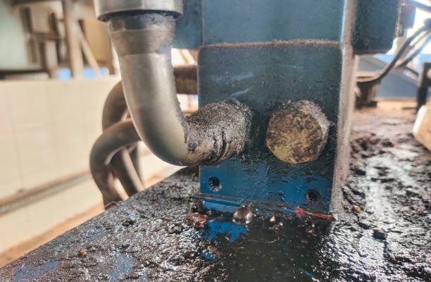
Hydraulic systems are at the heart of countless industrial operations—from manufacturing plants and construction machinery to aerospace and marine equipment. Within these systems, hydraulic flanges serve as robust connection points that maintain pressure integrity and prevent leakage of fluids like oil, water-glycol mixtures, or specialized hydraulic fluids. Hydraulic flange installation plays a critical role in ensuring the integrity and safety of hydraulic systems used across countless industrial operations
Why Flange Installation Matters
Improper flange installation is one of the top causes of hydraulic failures. Even a small misalignment, under-torqued bolt, or re-used gasket can result in:
- Leaks that reduce pressure and efficiency
- Environmental hazards due to oil spills
- Safety risks including fire hazards or equipment failure
- Costly downtime and emergency repairs
Given the high pressures (often up to 6,000 PSI), flange joints must be sealed with precision, strength, and durability.
How Flanges Fit in the System
Hydraulic flanges are typically used to:
- Connect pumps, valves, and motors to piping
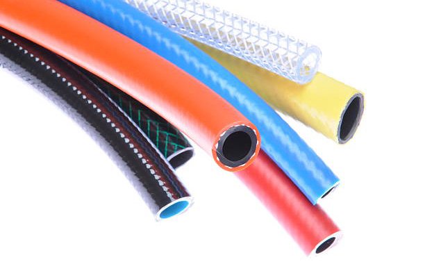
- Transition between rigid pipes and flexible hoses
- Isolate system components for service and testing
They are favored over threaded connections in high-pressure environments because they allow:
- Easy maintenance (components can be disassembled and reassembled)
- Higher pressure and temperature tolerance
- Better alignment and surface sealing options
Brief Historical Insight
Flanged connections were popularized in the 20th century as heavy machinery and hydraulics evolved. The development of SAE standards helped create global compatibility and safety norms across industrial sectors. Today, flange standards like SAE J518 and ISO 6162 ensure reliability and interchangeability across continents.
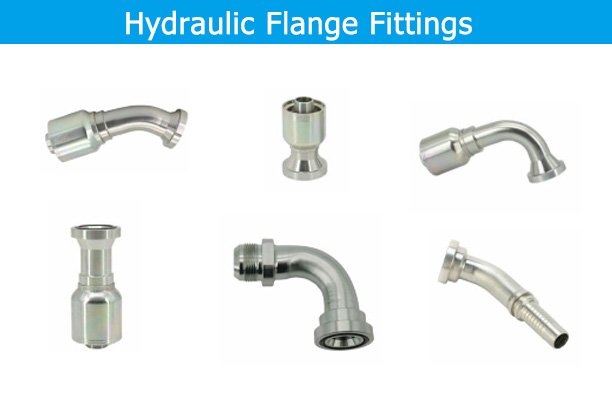
2. Types of Hydraulic Flanges
Flanges come in a variety of designs—each suited for specific pressure ratings, fluid compatibility, and installation environments.
SAE Flanges (Code 61 & Code 62)
Design: Feature four bolt holes, an O-ring groove, and a smooth or stepped sealing surface.
- Code 61 (low-pressure): Rated up to 3,000 PSI
- Code 62 (high-pressure): Rated up to 6,000 PSI
Materials: Carbon steel, stainless steel, and aluminum.
Applications: Excavators, injection molding machines, marine hydraulics.
Tips:
- Use with O-ring boss or flanged head fittings.
- Match Code 61 and 62 correctly—interchangeability is limited.
Split Flanges
Design: Two halves bolted together around the pipe or fitting.
Advantages:
- Ideal for retrofits
- Reduces downtime during installation
- Supports larger pipe diameters
Common Uses: Underground piping, confined areas, heavy mobile equipment.
Note: Always torque split flanges in small increments to prevent uneven compression.
Butt Weld Flanges
Design: Welded directly onto pipe ends for a permanent seal.
Advantages:
- No need for gaskets or O-rings
- Excellent under high stress, temperature, and vibration
Applications: Refineries, power plants, offshore rigs.
Caution: Welding must meet ASME standards to avoid heat-affected zone (HAZ) failure.
Threaded Flanges
Design: Internally threaded to screw onto matching pipe threads.
Limitations:
- Not suitable for vibration-prone or high-pressure systems
- Thread sealants may deteriorate over time
Use Cases: Temporary or low-pressure fluid transfer systems, light-duty equipment.
Specialty Flanges
- Blind Flanges: Seal pipe ends or test pressure retention.
- Socket Weld Flanges: For small-diameter high-pressure pipelines.
- Lap Joint Flanges: Allow pipe rotation for alignment; used with stub ends.
Each flange type should be selected based on:
- System pressure and temperature
- Fluid compatibility
- Maintenance requirements
- Installation constraints (space, orientation)
3. Tools and Materials Required
Having the right tools is essential not just for ease—but for precision and compliance.
Hand Tools
- Torque Wrench: Required for precise tightening. Choose digital or click-type models with ±4% accuracy.
- Hex or Allen Keys: For set screws or inner bolts.
- Socket Set: Ensure sockets match bolt grade (impact-rated for power tools).
- Open-End or Box Wrenches: For confined spaces.
Specialty Tools
- Hydraulic Flange Spreader: Safely separates flanges without damage.
- Dial Indicator or Runout Gauge: Measures flatness and alignment.
- Calipers/Micrometer: Check gasket thickness and bolt stretch.
- Bolt Lubricant (e.g., Moly Paste): Reduces friction to provide consistent torque.
Material Checklist
| Item | Specification Tips |
|---|---|
| Flanges | Match SAE or ISO type and material |
| Bolts | High-tensile (Grade 8.8–12.9); no rust or wear |
| Gaskets/O-Rings | New, compatible with fluid (e.g., Viton, Buna-N) |
| Anti-Seize Compound | Avoid galling on stainless bolts |
| Threadlocker | Use only where specified; never on lubricated bolts |
Tool Maintenance
- Calibrate torque wrenches every 6–12 months.
- Inspect sockets and wrenches for wear or cracks.
- Store O-rings in sealed bags to prevent degradation.
Safety Equipment
Always wear:
- Cut-resistant gloves
- Chemical splash goggles
- Face shield (especially during testing)
- Anti-static workwear in flammable environments
4. Pre‑Installation Preparations
Preparation determines the success of the job—rushing leads to future failures.
System Shutdown Procedures
- Hydraulic Power-Off: Isolate the system from its energy source.
- Depressurization: Open bleed valves or use pressure relief mechanisms.
- Verify Zero Pressure: Check with gauges—never assume a system is depressurized.
Inspection Checklist
| Component | Inspection Criteria |
|---|---|
| Flange Face | No scratches, dents, or embedded debris |
| Bolt Holes | Check for thread wear, cracking, or elongation |
| Gasket Groove | Clean, uniform depth, no warping or residual fluid |
| Old Components | Never reuse unless specified by OEM |
Use inspection tools like magnifying glasses, feeler gauges, or borescopes for internal pipe checks.
Surface Cleaning
- Use lint-free cloths and solvent like isopropyl alcohol.
- Avoid using abrasive pads that could score sealing surfaces.
- Compressed air may be used to blow out debris—but only in well-ventilated areas.
Installation Prep Documentation
Before moving to physical work:
- Review installation drawings and flange specs.
- Check that torque tables are up to date.
- Print flange maps and create a bolt torque record sheet.
5. Step-by-Step Hydraulic Flange Installation Guide
Proper hydraulic flange installation follows a meticulous sequence designed to ensure pressure integrity and long-term durability. Missing a step or using the wrong method can result in premature failure or unsafe operation.
Step 1: Align the Flange Faces
Use flange alignment pins or soft tools to bring the two mating surfaces into perfect alignment. There should be no angular offset or axial misalignment. Misaligned flanges increase stress on the gasket and can cause uneven loading across the bolts.
Step 2: Insert and Center the Gasket or O-Ring
Center the gasket carefully to avoid uneven compression. Some systems require adhesive-backed gaskets or locator rings to maintain position during assembly. Ensure the gasket matches the flange face type—flat, raised, or recessed.
For O-rings, lightly lubricate with fluid-compatible grease (e.g., silicone or hydraulic oil) to prevent pinching or twisting during bolt tightening.
Step 3: Install Bolts by Hand
Insert bolts and washers in all holes before tightening any of them. Finger-tighten each bolt in a cross-pattern sequence. This ensures even contact between the faces and reduces the risk of binding or bolt skewing.
Step 4: Torque in Multiple Passes
Use a calibrated torque wrench. Apply torque in three sequential steps:
- Pass 1: 30% of final torque
- Pass 2: 60% of final torque
- Pass 3: 100% of final torque
Follow a criss-cross star pattern when tightening bolts to evenly distribute pressure. On the final pass, repeat the torque on all bolts in a circular pattern to confirm even compression.
Step 5: Verify and Document
After the last torque pass:
- Check each bolt again for torque loss (may occur due to gasket settling).
- Record values on a bolt torque record sheet.
- Sign off for QA compliance, especially in regulated industries.
6. Common Mistakes During Installation
Even experienced technicians can make small oversights with big consequences. Understanding common mistakes helps avoid them during real-world installation.
Over-Tightening
Excessive torque crushes the gasket or O-ring, causing leaks and eventual failure. Over-compression can also warp the flange faces, creating uneven pressure points that distort the seal.
Under-Tightening
Insufficient torque results in a loose seal that may leak under pressure. Worse, vibrations or pressure surges can shake bolts loose, leading to gasket blowout or fluid ejection.
Ignoring Bolt Lubrication
Dry bolts create excessive friction, resulting in inaccurate torque readings. Always apply specified lubricant or anti-seize compound unless the procedure prohibits it.
Skipping Proper Bolt Sequence
Tightening bolts clockwise in order causes uneven flange seating. Always follow a star pattern to distribute stress symmetrically across the sealing surface.
Reusing Gaskets or Bolts
Used gaskets lose elasticity and may already be compressed or damaged. Similarly, bolts may have stretched beyond their yield point or have thread damage that reduces clamping force.
Using Incorrect Gasket Material
Not all materials are compatible with every fluid. For example, Viton is great for high-temp synthetic oils, but may degrade in phosphate ester fluids. Consult material compatibility charts before selection.
7. Torque Specifications and Bolt Patterns
Torque values ensure that the clamping force of the bolts is sufficient to compress the gasket or O-ring without over-stressing the flange or hardware.
Understanding Torque Principles
Torque is affected by:
- Bolt size and thread pitch
- Lubrication on bolt threads
- Flange material (steel vs. aluminum)
- Gasket or O-ring type
Always refer to manufacturer torque charts or standards such as SAE J518 or ISO 6162.
Standard Torque Table (Lubricated Bolts)
| Flange Size | Bolt Grade | Bolt Size | Torque (Nm) | Torque (Ft-lbs) |
|---|---|---|---|---|
| ½” | 8.8 | M10 | 35 | 26 |
| 1″ | 10.9 | M12 | 85 | 63 |
| 1½” | 12.9 | M16 | 200 | 147 |
| 2″ | 12.9 | M20 | 400 | 295 |
Bolt Pattern
Use the star or criss-cross pattern to distribute clamping load evenly. For 4, 6, or 8 bolt flanges, the sequence typically follows:
- Bolt 1 → Opposite bolt 2 → Perpendicular bolt 3 → Opposite bolt 4 → Continue in pattern
For flanges with more than 8 bolts, divide the circle into quarters and proceed diagonally across from one bolt to the next until all are tightened.
8. Safety Considerations and Best Practices
Hydraulic flange installation is not just a mechanical task—it involves high-stakes safety risks due to pressure, contamination, and proximity to moving machinery.
Personal Protective Equipment (PPE)
Always wear:
- Safety glasses or goggles (fluid sprays can cause blindness)
- Gloves resistant to oils and cuts
- Face shield during pressure testing
- Hearing protection in loud environments
Environmental Hazards
Hydraulic fluid leaks can cause:
- Slip hazards on work surfaces
- Fire risks with flammable oils
- Soil and water contamination
Always have spill containment kits nearby and clean up leaks immediately.
Hydraulic Testing Protocols
After installation:
- Conduct a low-pressure pre-test (e.g., 25% of system pressure).
- If no leaks are detected, increase to 100% working pressure.
- Monitor for 5–15 minutes under pressure.
- Use UV dye in fluid and blacklight for precise leak detection if necessary.
Avoid pressure testing with people nearby, and always stand to the side of the flange—never directly in front.
Quality Control Practices
- Use torque seals (mark bolts after final torque).
- Maintain flange installation logs for traceability.
- Train technicians annually on updated flange installation standards.
9. Troubleshooting Leaks and Failures
Despite best practices, hydraulic flange joints can still develop leaks or failures. Swift identification and response are critical to minimize downtime and avoid hazards.
Types of Leaks
Seepage or Misting
- Appears as a thin film of hydraulic fluid around the joint.
- Often caused by insufficient bolt torque or gasket compression.
- May worsen under high pressure or thermal cycling.
Dripping or Intermittent Leaks
- Visible drops or fluid trails.
- Commonly results from gasket misplacement, over-compression, or bolt stretch.
- Can also signal contamination or corrosion between mating surfaces.
Catastrophic Blowout
- Sudden ejection of hydraulic fluid or flange separation.
- Usually caused by complete O-ring failure, flange cracking, or improperly torqued bolts.
- Requires immediate shutdown and system inspection.
Root Cause Diagnosis
| Symptom | Possible Cause | Resolution |
|---|---|---|
| Uneven fluid film | Torque not evenly distributed | Retorque in star pattern |
| Gasket extruded or shredded | Over-tightened bolts | Replace gasket, retorque correctly |
| Threads stripped | Wrong bolt grade or overtightening | Replace bolts, verify torque values |
| Recurrent leaks | Misalignment or warped flange face | Use dial gauge or machine resurfacing |
| Cracking near bolt holes | Incorrect flange type for pressure rating | Upgrade to SAE Code 62 or forged design |
Leak Response Protocol
- Isolate and depressurize system.
- Wipe and dry area; inspect using UV dye if necessary.
- Check flange flatness with a straight edge.
- Remove and inspect the gasket for wear or chemical degradation.
- Replace damaged parts and retorque.
10. Maintenance Tips for Long-Term Performance
Proactive maintenance greatly extends the life of flange joints, improves system reliability, and helps prevent unexpected failures.
Routine Inspection Plan
- Daily: Visually inspect all flanged joints for leaks, drips, or loose bolts.
- Monthly: Retorque all critical connections in high-vibration environments (e.g., mobile equipment).
- Quarterly:
- Check gasket compression with thickness gauges if applicable.
- Inspect bolt heads and threads for corrosion or elongation.
- Annually: Conduct system-wide inspection using thermal cameras or ultrasonic leak detectors.
Gasket and Bolt Lifecycle Management
- Gaskets should not be reused and should be replaced after any disassembly.
- Store gaskets flat, in cool, dry conditions away from UV light and ozone sources.
- Bolts should be replaced after three torque cycles or if stretch exceeds 2% of length.
Digital Maintenance Tools
- Use bolt load monitoring sensors (e.g., strain gauges or tension bolts) for critical systems.
- Install RFID tags or QR codes on flanges to log installation and inspection history.
11. Industry Standards and Compliance
Following established standards ensures your flange installations meet safety, performance, and legal requirements—especially in regulated industries like oil & gas, pharmaceuticals, and aerospace.
Key Standards for Hydraulic Flanges
| Standard | Organization | Description |
|---|---|---|
| SAE J518 | SAE | Defines design, dimensions, and pressure ratings for hydraulic flanges (Code 61 & 62) |
| ISO 6162 | ISO | Specifies metric equivalents and testing requirements |
| ASME B31.1 | ASME | Power piping requirements, including flange installation criteria |
| API 6A | API | Equipment and flange specifications for oil and gas operations |
| DIN EN 1092 | DIN/EN | European flange standard for pressure vessels and piping systems |
Documentation and Recordkeeping
To stay compliant:
- Maintain flange installation checklists and torque logs.
- Archive material certifications for gaskets and fasteners.
- Document inspections with timestamped photos or audit software.
Training Requirements
- Technicians should undergo annual recertification on flange standards.
- In high-risk applications (e.g., oil rigs), third-party verification may be required.
12. Specialized Flange Installations
In certain industries and scenarios, standard flange procedures need to be adjusted or enhanced for safety and performance.
High-Pressure Systems (4,000–6,000 PSI and Up)
- Use Code 62 SAE flanges rated for 6,000 PSI or ISO 6162-2.
- All bolts should be Grade 12.9 or equivalent.
- Double O-ring gaskets or metal-reinforced gaskets may be needed.
- Torque verification must be done with digital logging tools.
Pro Tip: In mining or press equipment, consider using hydraulic bolt tensioners for uniform preload.
Underwater and Subsea Installations
- All components should be stainless steel or duplex steel to resist corrosion.
- Gaskets must be resistant to saline environments and galvanic corrosion.
- Flanges should be treated with marine-grade anti-seize and thread sealants.
Special Consideration: Use remotely operated vehicles (ROVs) with torque tools for deepwater applications.
Food & Pharmaceutical Processing
- Flange faces must be polished to sanitary-grade finishes (Ra ≤ 0.8 µm).
- Gasket materials must be FDA- or USP-compliant (e.g., PTFE, silicone).
- CIP (Clean-In-Place) and SIP (Steam-In-Place) compatibility is mandatory.
Aerospace Applications
- Aluminum flanges are often used for weight reduction.
- Torque must be verified to extremely tight tolerances (±2%).
- Systems may operate at extreme temperatures and pressures—material expansion must be considered.
13. Case Study: Flange Failure in a Mining Excavator
Background
A global mining operation in Western Australia reported a sudden hydraulic failure in a CAT 6060 excavator. The failure occurred during peak production hours and involved a 1.5” high-pressure hydraulic line supplying oil to the boom actuator.
Failure Overview
- System Pressure: 5,000 PSI
- Flange Type: SAE Code 62
- Fluid: Zinc-based hydraulic oil
- Environment: Dusty, high-vibration open-pit mine
Investigation Findings
- Gasket Reuse: The old gasket had been reused after a previous inspection, leading to reduced elasticity.
- Incorrect Bolt Torque: Only 3 of 4 bolts were torqued correctly; one was tightened by hand.
- No Inspection Log: No documentation or torque verification existed for the recent reassembly.
Damage and Cost
- 68 liters of hydraulic oil lost
- 3 hours of machine downtime
- Total production loss: $19,500
- Environmental cleanup and reporting triggered
Lessons Learned
- Always use new gaskets and inspect mating surfaces.
- Follow verified torque specs with calibrated tools.
- Record all flange installations with digital signatures or inspection stamps.
- Use redundant torque confirmation (e.g., two-person verification on critical joints).
This case underscores that even minor installation oversights can result in costly downtime, safety hazards, and environmental penalties.
14. Expert Tips for Seamless Installation
Drawing from years of fieldwork, here are advanced tips that professionals swear by:
Use Torque Seal Paint
Marking bolt heads after final torque not only prevents tampering but also makes future inspections faster. Any shift in the paint line signals a possible loss of clamping force.
Store Flanges and Gaskets Properly
Avoid UV, ozone, or high-humidity storage. Store rubber gaskets flat and metallic flanges in dry cabinets with rust inhibitors. Poor storage degrades performance before installation even begins.
Invest in a Digital Torque Logger
For critical flanges, use a digital torque wrench with logging capabilities. It automatically records bolt number, torque value, and timestamp, making QA and audits effortless.
Practice Cold Fit Simulations
Before assembling hot systems, conduct a cold-fit dry run to verify alignment, component orientation, and accessibility.
Control Vibration Post-Installation
Use pipe supports, clamps, or flexible hoses to minimize vibration-induced stress at flange joints.
Use a Flange Installation Map
Create a visual layout with flange numbers, torque specs, and inspection dates. This is especially useful for large systems and high-risk applications like oil rigs or power plants.
15. FAQs About Hydraulic Flange Installation
Q1: Can I use a single torque pass instead of incremental tightening?
A: No. Incremental torqueing distributes load evenly across the gasket and prevents warping or uneven compression.
Q2: Are aluminum flanges safe for high-pressure systems?
A: Only if the system is rated for it and environmental stress is low. For high-pressure and high-vibration setups, stainless or carbon steel is preferred.
Q3: How do I choose the right gasket material?
A: Base your selection on temperature, fluid type, and pressure. Consult chemical compatibility charts for Buna-N, Viton, EPDM, PTFE, etc.
Q4: How do I confirm that the flange faces are parallel?
A: Use a dial indicator or feeler gauge. Even minor misalignment can cause uneven bolt tension and leaks.
Q5: Should I lubricate the bolts before tightening?
A: Yes, unless specified otherwise. Lubrication ensures consistent torque readings and prevents galling, especially in stainless bolts.
Q6: How can I prevent flange leakage during startup?
A: Always pressure test the system, retorque bolts after warm-up, and inspect visually before reaching full operating pressure.
16. Conclusion
Hydraulic flange installation is both a science and a craft. It requires mechanical precision, attention to detail, and adherence to safety and industry standards. When executed correctly, flange joints will withstand high pressure, resist leaks, and extend the life of your hydraulic system.
By following the steps and insights in this guide—from selecting the right flange to torqueing bolts with care—you can:
- Reduce unplanned downtime
- Increase system efficiency
- Improve workplace safety
- Avoid costly repairs and environmental incidents
Whether you’re a technician in a mobile maintenance crew or an engineer managing plant hydraulics, this guide is your blueprint for successful flange installations—every single time.
FAQs
1. What torque should I use when installing hydraulic flanges?
Torque specifications vary depending on flange type, bolt size, and material. Always refer to SAE J518 or ISO 6162 standards, or the equipment manufacturer’s guidelines. Using a calibrated torque wrench is crucial to achieve the correct clamping force without damaging the gasket or flange.
2. Can I reuse the gasket or O-ring from a previous installation?
No. Gaskets and O-rings are designed for single use. Reusing them can lead to poor sealing, leaks, or complete failure. Always install a new gasket or O-ring to ensure maximum sealing integrity and system reliability.
3. Why is bolt tightening sequence important during flange installation?
Tightening bolts in a proper star or cross pattern ensures even compression across the gasket or O-ring. This prevents warping of the flange and reduces the risk of leaks. Skipping this step can cause uneven load distribution and premature failure.
4. What is the difference between Code 61 and Code 62 SAE flanges?
Code 61 flanges are designed for lower pressure applications (up to ~3,000 PSI), while Code 62 flanges are rated for higher pressures (up to ~6,000 PSI). They have different bolt hole patterns and are not interchangeable. Always verify the pressure rating before selection.
5. How often should I inspect and retorque hydraulic flange bolts?
Inspection should be performed monthly, or after the system has gone through temperature or pressure cycling. Retorque after initial startup and again after the first 24-48 hours of operation. In high-vibration or critical systems, more frequent checks may be necessary.
6. What causes hydraulic flange leaks even after proper installation?
Common causes include:
- Improper gasket material selection
- Contaminants on sealing surfaces
- Inadequate bolt torque
- Flange misalignment
- Temperature-induced expansion or contraction