Control valves are critical components in any industrial or manufacturing process. Acting as the gatekeepers of flow, they regulate variables like pressure, temperature, and liquid levels to ensure seamless operation. However, selecting and sizing a control valve isn’t as simple as picking one off the shelf. It requires a deep understanding of your system’s operational needs and a structured approach to finding the best match.
In this guide, we’ll dive into every aspect of control valve sizing and selection—covering the technical and practical considerations you need to know. You’ll learn how to calculate flow coefficients, understand valve characteristics, and make choices based on specific application requirements. Whether you’re new to the subject or refining your expertise, this guide will give you everything you need to confidently choose the right valve for your system.
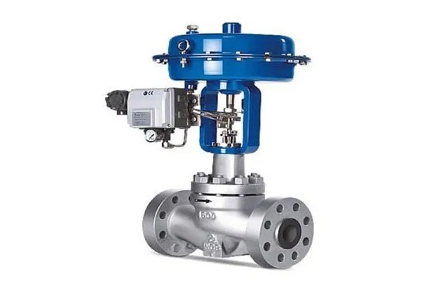
Key Components of a Control Valve
Understanding the key components of control valves is essential for proper sizing and selection:
- Actuator: Converts energy into mechanical motion to operate the valve.
- Valve Body: The main structure containing the fluid passage and seating surfaces.
- Positioner: Ensures the valve achieves the correct position based on the control signal.
Why Control Valve Sizing and Selection is Critical
A control valve that’s improperly sized or incorrectly selected can have far-reaching consequences, such as:
- System Inefficiencies: An oversized or undersized valve can cause poor flow control, energy loss, or even damage to other components.
- Reduced Reliability: Overworked or incorrectly installed valves wear out faster, leading to more frequent maintenance and downtime.
- Safety Risks: A control valve that fails to perform under extreme conditions could jeopardize the safety of your operation.
On the flip side, selecting and sizing the right control valve offers several benefits:
- Optimized performance: Precise flow control enhances system efficiency.
- Cost savings: Proper valve sizing reduces energy consumption and maintenance costs.
- Longevity: The right valve improves system reliability and reduces wear and tear.
Understanding Valve Sizing
Valve sizing involves determining the optimal dimensions and specifications for a valve to handle the required flow rate under given conditions. The process hinges on the valve’s flow coefficient (Cv), which measures the valve’s capacity to pass fluid.
Factors influencing valve size include:
- Process fluid properties
- System pressure and temperature
- Desired flow range
Key Steps in Control Valve Sizing
1. Understand Your System Requirements
Before you jump into calculations, gather all the necessary data about your system. You’ll need to determine:
- Maximum and minimum flow rates: Identify the operational range of your system.
- Pressure conditions: Collect information on upstream and downstream pressures, as well as the differential pressure across the valve.
- Fluid characteristics: Note the type of fluid (liquid, gas, or steam), its specific gravity, viscosity, and whether it’s corrosive or abrasive.
- Temperature: High-temperature fluids require different valve materials and designs than those for ambient temperatures.
Pro Tip:
Having a detailed process datasheet is essential—it saves time and ensures you won’t overlook critical parameters during sizing.
2. Calculate the Flow Coefficient (Cv)
The flow coefficient (Cv) measures how much flow a valve can handle for a given pressure drop. It’s a central metric in valve sizing.
Here’s the formula:
Cv = Q / √(ΔP/SG)
Where:
- Q = Flow rate in gallons per minute (GPM)
- ΔP = Pressure drop across the valve (psi)
- SG = Specific gravity of the fluid (dimensionless)
Example Calculation:
For a liquid with a flow rate of 100 GPM, a pressure drop of 10 psi, and a specific gravity of 0.8:
Cv = 100 / √(10 / 0.8)
Cv ≈ 100 / 3.54 ≈ 28.3
So, you’ll need a valve with a Cv of at least 28.3.
Why Cv Matters:
A valve with too low a Cv will restrict flow, while a valve with too high a Cv may cause control instability.
3. Determine the Desired Pressure Drop
The pressure drop across a valve determines how well it can control flow. Here’s a rule of thumb:
- Aim for a pressure drop of 10%-30% of the system’s total pressure drop for liquid applications.
- For gas applications, ensure the pressure drop remains below the critical pressure ratio to avoid choking.
Cavitation and Flashing:
Be cautious about cavitation (formation of vapor bubbles) and flashing (vapor bubbles that don’t re-condense). Both can damage valves and reduce their lifespan. If your calculations indicate these issues, consult with a valve specialist.
4. Select the Correct Valve Size
Contrary to common practice, valve size doesn’t always match pipe size. Instead, size the valve based on Cv requirements. Oversized valves lead to poor control because they operate near their closed position, while undersized valves restrict flow and cause high-pressure drops.
Pro Tip:
Choose a valve with a Cv slightly higher than your calculated Cv to allow for future capacity increases.
Considerations for Control Valve Selection
Once you’ve sized the valve, consider these factors to select the right type:
1. Valve Type
- Globe Valves: Known for their precision and stability, these are perfect for applications requiring tight flow control.
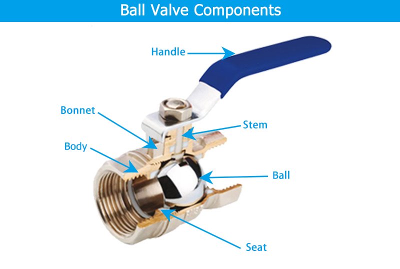
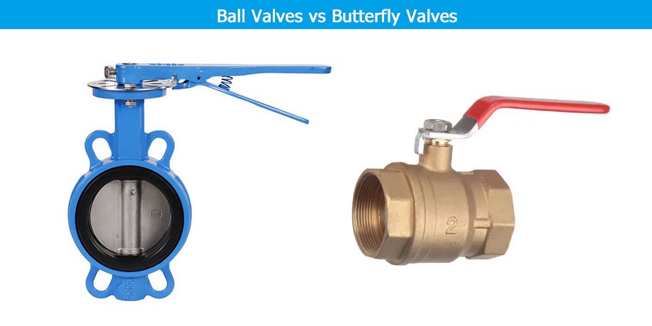
- Ball Valves: These offer high flow capacity and minimal pressure drop, making them ideal for on/off applications.
- Butterfly Valves: Cost-effective and compact, butterfly valves work well in large-diameter pipes.
2. Material Selection
Ensure the valve body, trim, and seat materials are compatible with the fluid and environmental conditions.
- For corrosive fluids: Stainless steel, Hastelloy, or titanium are common choices.
- For abrasive fluids: Hardened trim materials like tungsten carbide are ideal.
- For high temperatures: Materials like carbon steel or Inconel are suitable.
3. Actuation Options
Control valves can be actuated in different ways based on the level of automation and control required:
- Manual Actuation: Suitable for simple, low-cost operations where automation isn’t necessary.
- Pneumatic Actuation: Preferred for fast response times in automated systems.
- Electric Actuation: Ideal for precise control in remote or hazardous areas.
Common Mistakes to Avoid
- Neglecting Cv Calculation: Many engineers skip this critical step, leading to improper valve sizing.
- Undersizing Pressure Drop: Selecting a valve with too small a pressure drop can cause flow control instability.
- Ignoring Operating Conditions: Factors like fluid type, temperature, and pressure must always guide your selection process.
Conclusion
Control valve sizing and selection is both a science and an art. By following the steps outlined here—analyzing system requirements, calculating Cv, and selecting based on operational needs—you’ll ensure that your system operates efficiently, reliably, and safely.
Need more help? Check out manufacturer sizing tools, consult process datasheets, or reach out to an experienced engineer for advice.
FAQs
1. What is the difference between Cv and Kv?
Cv is the flow coefficient used in imperial systems (U.S.), while Kv is its metric equivalent. The relationship is: Kv = 0.865 × Cv.
2. Can I use the same valve for liquids and gases?
Not always. Different fluid types require valves with different flow characteristics and pressure drop considerations.
3. What is choked flow, and how can I avoid it?
Choked flow occurs when the velocity of the fluid reaches the speed of sound, creating a flow bottleneck. To avoid it, ensure the pressure drop across the valve is below the critical pressure ratio.
4. Can software tools replace manual sizing?
Software aids accuracy but requires validation against field conditions.
5. Why do valves cavitate, and how can it be avoided?
Cavitation occurs when pressure drops below vapor pressure. Proper sizing minimizes this risk.
6. What standards govern control valve selection?
ISA, ANSI, and API standards provide essential guidelines.