Introduction
When designing hydraulic systems, it’s tempting to treat hoses, fittings, and components as modular, independent parts—“Pick a hose rated for the pressure; pick a fitting that matches; connect them.” But real-world performance, durability, and reliability depend heavily on how those parts interact. That’s where integration becomes vital.
Why Integration Matters (Not Just Choosing Parts Independently)
- System-level stress interaction: Even if each part meets its rating, mismatched stiffness, flexing behavior, or thermal expansion can concentrate stress at interfaces.
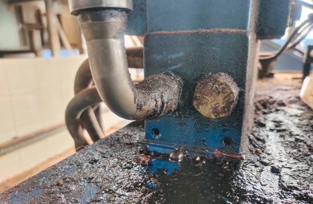
- Leak risk at boundaries: The junctions (hose-to-fitting, fitting-to-block, etc.) are the most vulnerable points—if tolerances or sealing strategies don’t align, leaks can originate there.
- Fatigue & life shortening: Repeated motion or pressure cycling will exploit weak integration paths (e.g. a hose bend near a rigid clamp, or misaligned fitting), leading to early failure.
- Hidden inefficiencies: Slight internal mismatches or turbulence from poor transitions can add friction losses, reducing effective power and responsiveness.
- Maintenance complexity: A system built without coherent integration makes inspection, replacement, and troubleshooting more error-prone.
Common Failure Modes from Poor Matching / Integration
- Hose delamination or internal cracking due to overflexing beyond the hose’s fatigue life
- Leaks caused by misaligned sealing surfaces, incompatible sealing types (e.g. trying to mate a flare with a face seal)
- Fitting fatigue fracture under bending loads not anticipated in the design
- Hose blow-offs when clamps or slack aren’t properly designed
- Abrasion damage from rubbing or vibration
- Premature material aging from temperature, chemical exposure, or incompatibility
What the Reader Will Learn
You’ll gain a complete, practical view of:
- Component selection: how to choose hoses, fittings, and materials that align
- Routing & layout: how to design hose paths and support to minimize stress
- Assembly & installation: techniques and checks to ensure integrity
- Testing & validation: how to confirm your integrated system is sound
- Maintenance & diagnostics: strategies to maximize lifespan and detect trouble
- Real-world lessons: illustrative examples that show what to do—and what not to do
1. Fundamentals of Hydraulic Systems
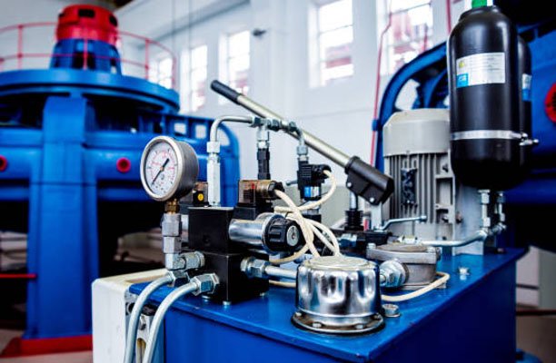
1.1 Components of a Hydraulic System
A hydraulic circuit includes several essential parts, all of which must work together:
- Reservoir (tank): stores fluid, allows aeration, handles heat dissipation
- Pump (gear, vane, piston): delivers flow at necessary pressure
- Valves (direction, pressure, flow, proportional): regulate where, how much, and at what pressure fluid goes
- Actuators (cylinders, motors): convert fluid power into mechanical motion
- Filters / strainers: remove particulates and protect sensitive components
- Accumulators: buffer pressure fluctuations, store energy, support velocity
- Piping, tubing, hoses: serve as conduits to connect all components
Within this architecture, hoses and fittings are critical conduits. They not only carry fluid, but also absorb motion, vibration, misalignment, and thermal expansion. They act as the “circulatory system”—if they’re weak, the whole machine suffers.
1.2 Operating Principles & Constraints
Pressure, Flow & Force
- Pascal’s Principle: pressure in a confined fluid is transmitted equally in all directions.
- Force output = pressure × actuator area.
- Flow rate (volume per time) determines actuator velocity.
- Pressure drop across lines and components reduces effective pressure at the load side.
Loss Mechanisms & Dynamic Effects
Frictional (viscous) losses in hoses, tubes, and fittings increase as velocity rises; in fact, they grow proportionally with the square of the velocity and also depend on surface roughness.
In addition, localized losses occur at bends, fittings, abrupt transitions, and restrictions, where flow disturbances are more pronounced.
Moreover, turbulence further amplifies these losses, so designers typically aim to maintain moderate velocities in order to minimize its impact.
Furthermore, pressure spikes or impulses may develop when switching valves or stopping actuators rapidly, creating transient overpressures that exceed the system’s steady-state pressure.
Finally, fatigue cycling becomes a concern, since repeated pressure fluctuations gradually cause mechanical fatigue in the hose reinforcement, fittings, and seals over time.
Thermal & Material Constraints
- High fluid temperature reduces viscosity (affecting flow control), softens seals, and accelerates aging of hose and fitting materials.
- Low temperature can stiffen hoses, making them less flexible and more brittle.
- Thermal expansion: materials and fluid expand, which must be accommodated in layout.
- Designers often use safety margins (e.g. a hose rated 4× the expected maximum pressure) and account for cyclic life.
Contamination & Cleanliness
Even tiny particles can damage valve spools, seals, and cause blockages. Maintaining fluid cleanliness and preventing contamination ingress during assembly and operation is essential.
2. Hose Selection: Types, Ratings & Compatibility
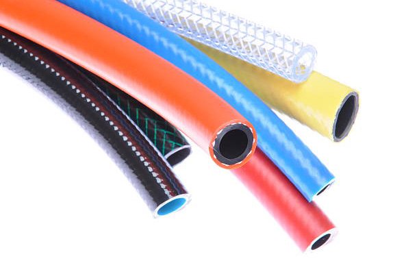
2.1 Hose Types & Reinforcement Structures
A hydraulic hose typically consists of:
- Inner tube (fluid contact)
- Reinforcement layers (wire braid/spiral or synthetic plies)
- Outer cover (abrasion, UV, ozone protection)
Reinforcement types:
- Braided (single or double): good flexibility at moderate pressures
- Spiral / multi-spiral: supports higher pressures, stiffer
- Textile or hybrid: lower pressure or specialty uses
Standards like SAE 100R define categories:
- SAE 100R1 / R2: braided designs
- SAE 100R12 / R13: spiral or multi-spiral designed for high pressure
Construction differences influence flexibility, size, weight, and rating.
Skive, no-skive, interlock systems:
- Skive: outer cover is cut back at the hose end so fitting can grip firmly.
- No-skive: retains full outer jacket; fitting and crimping solutions ensure grip.
- Interlock systems: provide a mechanical engagement between the fitting and the hose, which makes them especially suitable for heavy-duty or high-dynamic hydraulic applications.
2.2 Pressure, Temperature & Fluid Compatibility
- Working (rated) pressure: the maximum continuous operating pressure.
- Burst pressure: the threshold at which the hose fails (usually many times the working pressure).
- Always include margin for spikes and pressure surges.
- Impulse rating: how many cycles of pressure the hose can endure; crucial in systems with frequent switching.
- Temperature limits: hoses have operational temperature ranges (e.g. –40 °C to +100 °C). Operating outside reduces life.
- Fluid compatibility:
• Mineral oil systems require compatible elastomers (e.g. nitrile, HNBR)
• Synthetic fluids or esters may require fluoroelastomers (e.g. Viton)
• Biodegradable fluids may require special linings
Compatibility of seals, hoses, and cleaners must all be checked.
2.3 Bend Radius, Flexibility & Routing Constraints
- Every hose has a minimum bend radius determined by its construction and size. If the bend is tighter than this limit, it increases stress on the reinforcement layers and eventually leads to fatigue.
- Dynamic systems (moving machinery) must use hoses rated for cyclic flexing.
- Avoid twisting during installation—torsion weakens structural integrity.
- Use elbows or fittings to ease tight routing around obstacles, but never allow the bend to violate the hose’s specified radius.
- Designers must allow slack (looping) to absorb thermal expansion or movement.
3. Fittings & Connectors: Types, Standards & Sealing Methods3.1 Common Fitting Styles & Standards
In hydraulic design, fitting systems must adhere to multiple standards to ensure compatibility, performance, and safety. In particular, the most common styles include:
- Threaded fittings:
- NPT / NPTF: tapered thread, seal through thread deformation
- ORB (O‑Ring Boss): straight thread with O‑ring seal
- ORFS (O‑Ring Face Seal): face seal with O‑ring compressed at the face
- JIC / 37° flare: common in North America
- BSP / BSPT: used internationally, different thread and sealing design
- ISO / Metric / DIN style fittings: often use 60° cones, flareless or sealing faces
- Flange systems:
- E.g. four-bolt flange designs (ISO 6162 style, F‑series, etc.) for high-flow, high-pressure or machine interface points
- Banjo fittings: compact, swiveling in limited clearance spaces
- Quick‑connect couplings: enable rapid connection/disconnection without tools (valuable in modular or maintenance-intensive systems)
While each standard offers specific advantages, it also entails trade-offs in leak tolerance, vibration resistance, ease of assembly, cost, and size.
3.2 Sealing Methods
- Metal‑to‑metal seal: two machined surfaces mate directly; tight tolerances required.
- Soft seals (O‑rings, bonded seals): more forgiving, better at handling slight misalignment or vibration.
- Flare seals: male flare fits into female seat; often used in JIC / 37° systems.
- Face seals: seal at the face plane, typically via O‑ring compressed between flat faces (common in ORFS).
- Tapered threads: rely on thread deformation and sealants to prevent leaks.
Choosing the appropriate sealing method is crucial for leak-free, vibration-tolerant performance.
3.3 Material Selection & Corrosion Resistance
- Carbon steel: strong and common, but needs protective coating in corrosive environments.
- Stainless steel: resists corrosion, ideal for outdoor, marine or chemically aggressive environments.
- Brass / bronze: used in lower-pressure or hydraulic support lines.
- Aluminum: lightweight, but limited strength at high pressure.
- Platings / coatings (zinc, nickel, cadmium, etc.) help protect against corrosion, galling, or surface wear.
Selecting materials compatible with fluid, environment (humidity, salt, chemicals), and mechanical loads is essential.
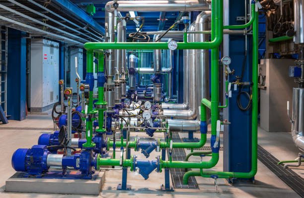
4. System Integration: Layout, Routing & Sizing
4.1 Proper Hose & Component Layout
- Minimize line length and avoid unnecessary routing to reduce pressure drop.
- Avoid twists or torque in hose installations.
- Start bends at a distance from fittings, not immediately adjacent, to reduce stress concentrations.
- Slack loops or gentle curves allow for movement, expansion, and vibration cushioning.
- Respect alignment: misalignment transmits bending loads into connections.
4.2 Pressure Drops & Flow Considerations
- Calculate expected flow rate and velocity in each segment.
- Use hydraulic fluid tables and formulas to estimate pressure drop per length.
- Upsize hoses in long runs or high-flow branches to mitigate losses.
- Factor in pressure loss coefficients for bends, elbows, or flow disturbances.
- Monitor and control Reynolds number for whether the flow is laminar or turbulent.
4.3 When to Use Pipe, Tube vs Hose
- Rigid pipe / tube: use in static, stable runs where vibration or movement is negligible; excels at minimal maintenance and minimal leakage risk.
- Hose: ideal for segments that require flexibility, movement, vibration isolation, or modular connections.
- Use transition fittings at the interface between rigid and flexible sections; ensure precise alignment and appropriate sealing.
4.4 Support, Clamping & Strain Relief
- Secure hoses at intervals with clamps to prevent flapping or contact with surfaces.
- Use protective sleeves or abrasions guards in areas where hoses might rub.
- Use bend restrictors near fitting ends to prevent overbending.
- Ensure clamps do not pinch or distort hose; leave slight slack to avoid binding.
5. Assembly, Installation & Quality Assurance
5.1 Pre-Assembly Preparation & Cleanliness
- Flush hoses with compatible fluid or clean air to remove debris.
- Inspect ends for frayed reinforcement strands, burrs, or damage.
- Keep tools and environment clean to avoid contamination at sealing surfaces.
- Cap open ends until the final assembly moment.
5.2 Crimping & Field Assembly
- Use correct crimp tools and dies, specific to the hose and fitting type.
- Follow manufacturer insertion-depth guidelines to ensure proper seating.
- Measure crimp dimensions and verify they fall within tolerance.
- Avoid mixing hose/fitting brands unless compatibility is confirmed—dimensions or tolerances may differ.
5.3 Installation Best Practices
- Route hoses in their naturally relaxed shape—not forced.
- Apply correct torque to threaded fittings; under-torque causes leaks, over-torque causes damage.
- Tighten in proper sequence to avoid inducing stress.
- After installation, pressure-test before putting system into service.
5.4 Testing & Validation
- Hydrostatic test: pressurize to a safe over-pressure (e.g. 1.25× working pressure) to check for leaks or weaknesses.
- Impulse cycling test: subject the system to repeated pressure cycling to simulate extended use.
- Use leak detection methods such as dye, UV tracer, or ultrasonic scanning to locate fine leaks.
- Monitor behavior under real operating conditions for temperature rise, pressure drop, or signs of stress.
6. Maintenance, Diagnostics & Lifespan Considerations
6.1 Common Failure Modes & Their Causes
- Abrasion: constant rubbing, vibration, or contact with surfaces.
- Fatigue / flex life exhaustion: repeated bending beyond design limits.
- Ozone / UV damage: cracking over time on exposed hose surfaces.
- Corrosive damage: fittings or hose exteriors attacked by chemicals, salts, moisture.
- Improper installation stress: twist, pinch, tight bends, insufficient slack.
- Transient pressure spikes: overloading hoses or fittings beyond design margins.
6.2 Inspection & Preventive Maintenance
- Conduct visual checks regularly to spot cracks, bulges, blistering, abrasions, or soft spots.
- Use ID tags or date stamps so you can track hose age and usage.
- Check for slack, rubbing, bending angles, and ensure hoses are not taut.
- Define replacement criteria not solely by time but by observed condition, usage cycles, or manufacturer guidance.
6.3 Repair Strategies & Replacement Guidelines
- When repairs are needed, use approved repair kits or assemblies from the same system or manufacturer.
- Avoid mismatching fittings or cutting and reusing old hose ends.
- In high-risk systems, proactively replace entire assemblies rather than patching them.
- Use replacement intervals driven by duty cycles, environment, and observed wear rather than arbitrary timelines.
7. Case Examples
7.1: Tight Hose Bend Leading to Failure
A construction machine had a hydraulic line routed sharply near a corner with radius below spec. Under cyclic motion, the hose’s reinforcement deteriorated, and the hose ruptured prematurely after a relatively short service life. The redesign introduced a gentler curve, used proper elbows, and respected minimum bend radius. The revised layout held up over many times longer service hours.
7.2: Incompatible Fittings Causing Micro-Leaks
A factory hydraulic press used hoses from one vendor and fittings from another. Slight mismatches in tolerances and sealing surfaces led to intermittent micro-leaks under vibration. A full replacement using a matched hose-fittings system with consistent tolerances resolved the leaks entirely.
7.3: Under-crimped Hose Blow-Off
During maintenance, a technician used a worn crimp die and insufficient crimp compression. Under load, the hose popped off the fitting at about half of the system’s rated pressure. After retraining and calibrating crimping equipment, subsequent installations passed pressure tests with no failures.
Conclusion
Designing a durable, efficient, and reliable hydraulic system is more than selecting components rated for the job—it’s about integrating them in a smart, system-wide way. Focus on:
- Compatibility in pressure, temperature, mechanics, and materials
- Thoughtful layout and routing to minimize stress
- Clean, correct assembly and validation
- Vigilant inspection and proactive maintenance
By treating hoses, fittings, and components as interconnected parts of a living system, you build machines that last longer, perform better, and fail far less often.
FAQs
1. Can I mix different brands of hoses and fittings?
No. Mixing brands can cause leaks or hose blow-offs because not all parts are made to the same size or standards. Always use hoses and fittings from the same brand for safety.
2. Why did my hydraulic hose leak even though it was tight?
A hose can leak if it’s over-tightened, under-tightened, has a damaged seal, or the wrong fitting type was used. Always check for the correct torque and seal.
3. How do I know which hydraulic hose to use?
Choose a hose based on:
- System pressure
- Fluid type
- Temperature range
- Flexibility needs
Follow the manufacturer’s guide or ask a hydraulic expert.
4. What’s the safe way to bend a hydraulic hose?
Don’t bend it too sharply. Always follow the minimum bend radius listed by the hose manufacturer. Bending too much can damage the hose inside.
5. How often should I check or replace hydraulic hoses?
Inspect hoses every few months. Replace them if you see cracks, leaks, bulges, or wear. Many hoses need replacing every 1 to 2 years, depending on use.
6. What’s better: crimped or reusable fittings?
- Crimped fittings are stronger and better for high pressure.
- Reusable fittings are handy for quick repairs but not for all systems.
Crimped is safer for long-term or high-demand use.