Introduction to Hydraulic Flanges
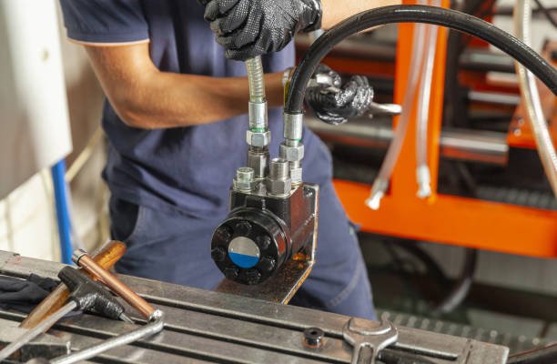
Hydraulic Flange Installation is essential for creating sealed, durable connections between hoses, tubes, and pipes in high-pressure hydraulic systems, ensuring reliable performance under extreme operating conditions.
Flanges are particularly common in industries such as construction, manufacturing, mining, and aerospace, where fluid transfer reliability is paramount. By offering flexibility, easy maintenance, and strong sealing capabilities, hydraulic flanges help prevent leaks and ensure system integrity.
The proper installation of hydraulic flanges is essential to maintaining system efficiency and safety. Even minor misalignments or incorrect torque settings can result in costly downtime, fluid leakage, or catastrophic system failure.
Types of Hydraulic Flanges
Several types of hydraulic flanges exist, each designed to meet specific pressure and configuration requirements. Understanding these variations is key to selecting the right flange for your application.
SAE Code 61 and Code 62 Flanges
These are the most commonly used hydraulic flanges. SAE Code 61 flanges are rated for lower pressure applications (up to 3,000 psi), while Code 62 flanges are designed for high-pressure systems (up to 6,000 psi).
Split Flanges
Split flanges come in two parts and are ideal for tight spaces or retrofitting existing systems. They offer easier installation and maintenance without the need to disassemble large components.
Threaded vs. Welded Flanges
Threaded flanges are easier to install but are more prone to leaks over time. Welded flanges provide a permanent, leak-proof connection ideal for high-stress environments.
O-Ring Face Seal (ORFS) Flanges
ORFS flanges use a captured O-ring groove for an optimal seal. They are particularly useful in systems requiring vibration resistance and leak-free performance under pressure fluctuations.
Key Components Required for Flange Installation
Successful flange installation depends on more than just the flange itself. Several components work together to ensure a secure, pressure-resistant joint.
Bolts and Clamps
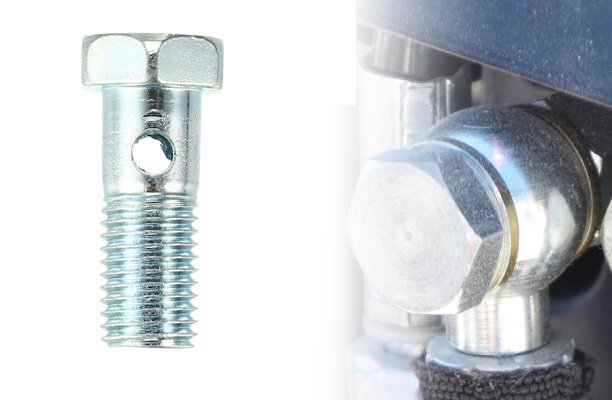
High-strength bolts are essential for holding flanges together. Clamps or clamps halves help secure the flange connection, particularly in split flange assemblies.
O-Rings and Seals
O-rings are vital for leak-proof sealing. It’s crucial to use the correct material and size, typically specified by the flange manufacturer, to ensure compatibility with the hydraulic fluid and pressure rating.
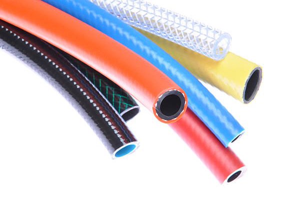
Hydraulic Hoses or Tubes
The hoses or tubes connected to the flanges must be clean, free from damage, and correctly sized. Proper alignment with the flange prevents stress and eventual failure.
Pre-Installation Preparation
Before beginning hydraulic flange installation, thorough preparation is crucial to ensure a reliable and safe connection. Inadequate preparation is one of the leading causes of flange failures and system leaks.
Cleaning and Inspecting Components
All components—including the flange, O-ring, hose ends, and bolts—should be free of dirt, debris, and metal shavings. Contaminants can compromise the seal and damage the system. Inspect for corrosion, pitting, or irregularities that could affect sealing surfaces.
Verifying Compatibility and Pressure Ratings
Confirm that all parts are rated for the pressure level of the system. Using mismatched components can lead to catastrophic failures. Pay special attention to pressure ratings, materials, and temperature tolerances.
Aligning Flanges and Hose Assemblies
Misalignment puts stress on the flange and connected hoses, which can lead to premature wear or leaks. Use alignment tools if necessary to ensure a straight, centered fit between flange faces and hydraulic components.
Tools Needed for Installation
The right tools are essential for accurate and efficient flange installation. Inappropriate tools can lead to improper torque or damage to sealing surfaces.
Torque Wrench and Sockets
A calibrated torque wrench is required to tighten bolts to the manufacturer-specified torque. Always use sockets of the correct size to prevent stripping bolt heads or damaging threads.
Flange Spreaders
These are used to separate flanges safely and evenly without damaging the flange faces. They’re particularly useful during disassembly and re-installation in maintenance operations.
Lubricants and Sealants
Anti-seize compounds or approved hydraulic-compatible lubricants reduce bolt galling and allow more accurate torque application. Sealants may be used in specific applications, but always follow manufacturer guidelines to avoid contamination.
Inspection Mirrors and Alignment Tools
These help technicians visually inspect hard-to-reach areas and confirm proper alignment. Ensuring all parts are flush and centered is key to leak-free operation.
Step-by-Step Hydraulic Flange Installation Process
A structured installation process ensures each component is correctly fitted and secure. Below is a general step-by-step procedure for installing hydraulic flanges:
Step 1: Aligning Components
Position the flange halves around the connection area and make sure the hose or tube is correctly seated. Check that bolt holes are aligned and no part of the O-ring groove is obstructed.
Step 2: Installing O-Ring and Seals
Lubricate and place the O-ring in the designated groove on the flange face. Ensure it sits evenly and is not twisted or pinched, as this could cause leaks once pressurized.
Step 3: Bolting Procedure
Insert bolts into the flange holes and begin tightening them in a cross-pattern. This helps distribute pressure evenly and avoids flange warping. Do not fully tighten any bolt until all bolts are seated.
Step 4: Final Torque Specifications
Use a torque wrench to tighten each bolt to the recommended specification. Refer to manufacturer torque charts to avoid over- or under-tightening, which can damage the seal or create unsafe conditions.
Torque Specifications and Tightening Sequence
Applying the correct torque and following a proper tightening sequence are critical for ensuring a secure, leak-proof hydraulic flange connection. Improper torque can result in seal damage, flange distortion, or bolt failure.
Importance of Proper Torque
Over-torquing can compress the O-ring too much, leading to premature failure. Under-torquing may cause insufficient sealing and fluid leaks. Always use a calibrated torque wrench to apply the specified values.
Cross Bolt Pattern
To evenly distribute load and prevent flange warping, always tighten bolts in a cross or star pattern. This sequence minimizes stress concentrations and allows the O-ring to seat evenly across the entire flange face.
Torque Charts by Flange Type and Size
Manufacturers typically provide torque specification charts based on flange type (SAE Code 61/62, ORFS, etc.) and bolt size. Refer to these charts for accurate values. For example, a 3/4\” SAE Code 61 flange with 1/2\” bolts may require 62 lb-ft of torque.
Common Installation Mistakes and How to Avoid Them
Even experienced technicians can make errors during installation. Understanding the most common mistakes can help prevent costly and dangerous issues.
Over-Tightening Bolts
Applying too much torque can deform the flange or crush the O-ring, resulting in leaks. Use proper tools and double-check specifications before final tightening.
Using Incorrect O-Rings
Substituting O-rings with incorrect materials or sizes compromises chemical resistance and sealing ability. Always use manufacturer-recommended O-rings and verify compatibility with the hydraulic fluid.
Misalignment and Cross-Threading
Improper alignment can stress fittings and reduce service life. Cross-threading bolts during installation not only damages threads but also weakens structural integrity. Always begin threading by hand to ensure proper alignment.
Leak Testing and Inspection Post-Installation
After installation, it’s essential to test the system for leaks and conduct a thorough inspection. Early detection of issues can prevent failures and costly downtime.
Types of Leak Tests
- Bubble Test: Spray a soap solution on the flange connection and watch for bubbling, which indicates a leak.
- Pressure Test: Pressurize the system and monitor pressure levels for any drop over time.
- Dye Penetrant Test: Use UV-reactive dye to identify hairline leaks or flaws in the sealing surface.
Visual Inspection Checklists
Inspect for uneven bolt torque, flange face alignment, O-ring compression, and signs of hydraulic fluid seepage. Also, confirm there are no visible cracks or corrosion on the flange surface.
Documentation of Test Results
Keep detailed records of leak tests and inspection findings for compliance, future reference, and maintenance planning. Include torque values, test methods, and any corrective actions taken.
Maintenance Best Practices
Proactive maintenance of hydraulic flanges can significantly extend system life, reduce downtime, and ensure continued safety and performance. Regular checks and servicing help catch issues early before they evolve into costly failures.
Routine Checks for Wear and Leaks
Inspect flange connections regularly for fluid seepage, bolt loosening, and O-ring degradation. A small leak today could indicate an impending failure. Check for signs of corrosion, especially in high-moisture environments.
Retorquing Intervals
Periodic retorquing is often required, especially after the first few hours of operation in new systems. Refer to equipment manuals for recommended intervals and torque specifications.
Replacing Worn Seals and Gaskets
Always replace seals and O-rings during maintenance rather than reusing old components. Reusing aged or compressed seals increases the risk of leaks and system inefficiency.
Safety Tips During Installation
Hydraulic systems operate under extremely high pressures, which can pose serious risks during installation and maintenance. Following safety protocols is non-negotiable for all personnel working with hydraulic flanges.
Personal Protective Equipment (PPE)
Always wear PPE including safety goggles, gloves, and protective clothing to prevent injuries from fluid sprays or sharp edges. In some environments, additional PPE like face shields may be necessary.
Lockout-Tagout Procedures
Before starting installation or maintenance, isolate the hydraulic system using proper lockout-tagout (LOTO) procedures. This prevents accidental pressurization and ensures a safe working environment.
Avoiding High-Pressure Exposure
Never inspect a hydraulic flange by hand while the system is pressurized. Even small leaks can eject fluid at high velocities, causing injection injuries. Use approved detection methods and maintain a safe distance during pressurization tests.
Troubleshooting Hydraulic Flange Issues
Even with careful installation and maintenance, problems can arise. Understanding common issues and how to address them can minimize downtime and ensure rapid resolution.
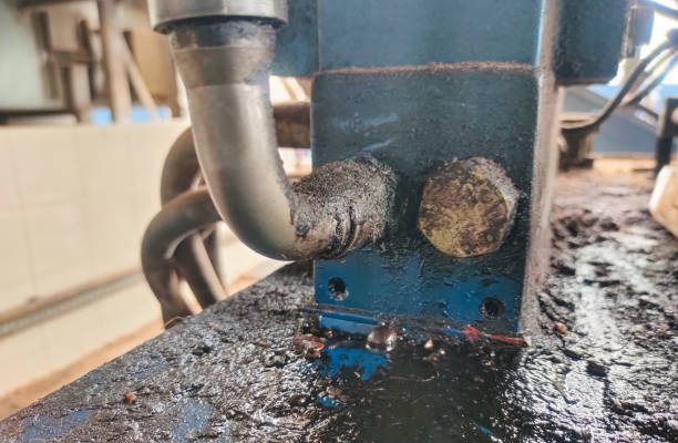
Diagnosing Leaks
Leaks may stem from improper torque, damaged O-rings, or cracked flange faces. Use a systematic approach—start by checking torque values, then inspect the O-ring and sealing surfaces for wear or debris.
Identifying Flange Damage
Warped or corroded flanges will not seal properly. Inspect for hairline cracks, pitting, or uneven mating surfaces. Use precision tools like feeler gauges and straightedges for accurate assessment.
Field Repair vs. Component Replacement
Minor issues like worn O-rings can often be repaired on-site. However, significant flange damage or repeated leak incidents may require complete component replacement to restore reliability and safety.
Industry Standards and Compliance
Hydraulic flange installation must adhere to established industry standards to ensure safety, performance, and compatibility across systems and manufacturers. Compliance is especially critical in regulated industries such as aerospace, defense, and oil & gas.
ISO, SAE, and ASME Standards
Common standards include ISO 6162, SAE J518, and ASME B16.5. These provide specifications for flange dimensions, pressure ratings, and material requirements. Always verify the flange meets the applicable standard before installation.
Documentation and Traceability
Keep detailed records of installation, inspection, and maintenance activities. This is especially important for quality control audits, warranty claims, and equipment certification. Traceability helps identify defective batches and prevent systemic failures.
Certification Requirements
Technicians installing hydraulic systems may require specific certifications, especially in industries governed by safety regulations. Certifications from ISO, ASME, or industry-specific programs help ensure competence and accountability.
Case Studies and Real-World Applications
Hydraulic flanges are used in a wide array of applications, from heavy machinery to advanced aerospace systems. Real-world examples highlight the critical role of proper installation in performance and safety.
Mobile Machinery
Construction equipment like excavators and loaders rely on hydraulic flanges for actuating arms, buckets, and attachments. Poor installation can lead to catastrophic hydraulic failure during operations.
Industrial Equipment
Manufacturing lines and hydraulic presses use flanges to connect high-pressure systems. Downtime due to a leak can halt production and lead to financial losses, making reliable flange installation essential.
Aerospace and Marine Applications
Flange systems in aircraft and ships must meet strict safety and reliability standards. In these environments, precision installation and documentation are critical due to the high-risk nature of operations.
Conclusion
Hydraulic flange installation is a foundational skill in fluid power systems that directly impacts performance, safety, and longevity. From selecting the correct flange type to applying the right torque and maintaining regular inspections, every step is crucial.
By following best practices, using the proper tools, and adhering to industry standards, technicians can ensure a secure, leak-free connection that supports system integrity under even the most demanding conditions.
Whether you’re working in construction, manufacturing, aerospace, or marine operations, taking the time to install flanges correctly will save money, reduce downtime, and most importantly—keep personnel safe.
FAQs
1. What is the difference between SAE Code 61 and Code 62 flanges?
SAE Code 61 flanges are designed for medium-pressure applications up to 3,000 psi, while Code 62 flanges are built for high-pressure environments up to 6,000 psi. They differ in bolt pattern and thickness.
2. Can I reuse O-rings during maintenance?
No. Reusing O-rings is not recommended as they may be compressed, cracked, or chemically degraded. Always install new O-rings to ensure a proper seal.
3. What happens if I over-tighten flange bolts?
Over-tightening can crush the O-ring, distort the flange, and lead to leaks or component failure. Always use a calibrated torque wrench and follow manufacturer torque specifications.
4. How do I know if a flange is misaligned?
Signs of misalignment include uneven bolt holes, difficult bolt insertion, stress on hoses, and early leaks. Use alignment tools and inspect visually before tightening.
5. What are common symptoms of a hydraulic flange leak?
Common signs include visible fluid at the joint, reduced system pressure, oily residues around the flange, and hydraulic system noise. A leak test is the best way to confirm the issue.